CMPUT 503 Lab 2 report
Group members: Truong Pham, Nicolas Ong, Martin McLaren.
Ros Basics
ROS topics Topics are named data buses where nodes can publish to. ROS uses publisher/subscriber patterns in which a node can publish date to a topic, and other nodes can subscribe to the same topic to receive published data through a callback. It is similar to a polling system.
ROS nodes A node is a process instance that communicates with other nodes through topics and messages. Each node is usually responsible for controlling a specific sensor or to do a specific task.
ROS services The subscriber/publish model does not support one-to-one communication. ROS services allows request/reply communication model similar to client/server model. A node can request for information from another node using services
ROS messages ROS nodes publish messages to topics. ROS message can be primitive data types like float, int, boolean, etc, or a complex data types like arrays. ROS message can contain a header to include meta datas.
ROS bags
rosbag is a node that records data from topics that it subscribes for offline analysis.
We use rosbag record to start recording datas from specified subcribed topics.
How it works together
Camera annotation
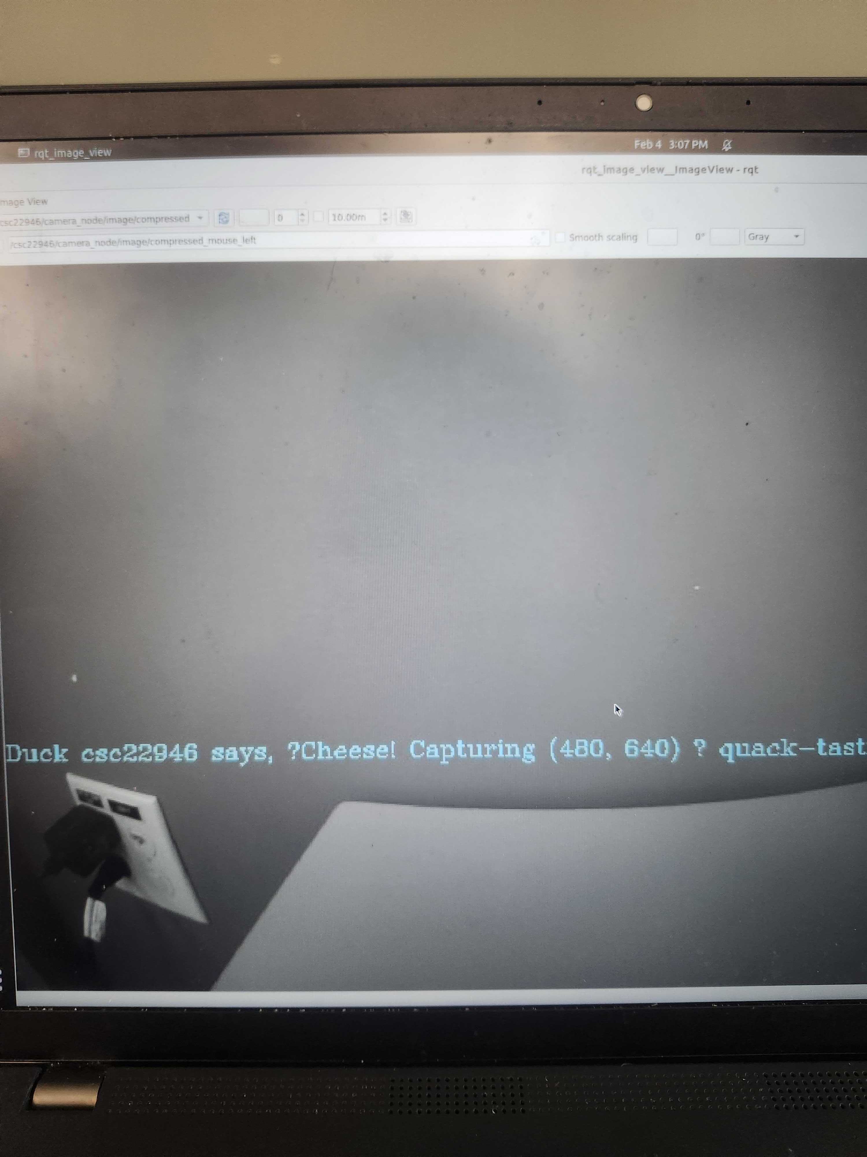 We subscribed to
 ../camera_node/image/compressed topic, and we let OpenCV does the grayscaling.
We published to the same topic.
Challenges
Initially, rqt_imag_view did not render the grayscale image correctly. We realized later that grayscaling the image removes the last channel.
(H, W, 3) -> (H, W).
After reshaping the image back to (H, W, 3) using gray_image = np.stack((gray_image,)*3, axis=-1), it works.
On aside, we couldn’t figure out how to publish to our own custom topic.
Any topic aside from ../camera_node/image/compressed caused image corruption.
Making the robot move
Robot Kinematics
Since we did not have each wheel’s velocity to compute \(\Delta\theta\), we opt to compute it using only change in distance.
We reference equations in this medium article.
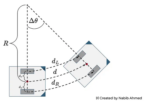 We keep track of the world’s frame \([x_I, y_I, \theta_I]\) at each timestep by mapping from robot’s frame \([x_r, y_r, \theta_r]\).
We assume that \(\theta_r = \theta_I\).
We keep track of the world’s frame \([x_I, y_I, \theta_I]\) at each timestep by mapping from robot’s frame \([x_r, y_r, \theta_r]\).
We assume that \(\theta_r = \theta_I\).
\(d_w\) is the distance between the wheel and the center of robot.
We get this from rosparam /kinematics_node/baseline.
\([x_I, y_I, \theta]_t = [x_r, y_r, \theta_r] \cdot R^{-1} (\theta)^T\)
Where
We solve for this system of linear equation by multiplying (1) with -1
\[\begin{align*} & -d_{L} = -R\cdot \Delta\theta + d_w \cdot \Delta\theta \\ + & d_{R} = R\cdot \Delta\theta + d_w \cdot \Delta\theta \\ \hline & d_R - d_L = 2\cdot d_w \Delta\theta \end{align*}\]Thus \(\Delta\theta = \frac{d_R - d_L}{2\cdot d_w}\) \(\Delta\ x = \frac{d_R + d_L}{2}\) \(\Delta\ y = 0\)
All together,
\[[x_I, y_I, \theta]_t = [x_I, y_I, \theta]_{t - 1} + R^{-1} (\theta)^T \cdot[\Delta x, 0, \Delta\theta]\]Challenges
- We struggle to compute the \(\Delta\theta\) initially since it required each wheels’ velocity. We were eventually able to find formlas to compute \(\Delta\theta\) using only distance traveled by each wheel, which can be computed using ticks.
- Since we had to update the change in robot frame in the background. We opt to put these calculations in a while loop, running in a separate threads. We could’ve calculate these in a callback, but we could not find information on a realiable topic to do attach a callback to do calculations.
- We realize that our calculated \(\Delta\theta\) was smaller than expected. Therefore, we did \(\Delta\theta = 1.5 cdot \theta\) to scale to the expected value.
- The bot does not drive in a straight line despite retuning the trim value. We can overcome it by making publishing an imbalance velocity to each wheel to correct it.
Why is there difference between the actual and desired location?
Perhaps there was difference in the theoretical and the actual robot location is because of the discrepancies in tick encoder sensors or other constants. We did not measure the wheel radius nor the distance between the wheels, so we used the default value in the kinematic file (0.325 and 1). On aside, terraine fraction can also mess up with our maths.
What speed did you use? What happens when you increase or decrease the speed?
We used constant 0.5 velocity for each wheels. When we increased the speed, we find that the duckiebot is more stable. Perhaps it overcame small bumps on the terrain that could otherwise affect the wheels.
Turn the Duckiebot task
To spin duckiebot, we spun each wheel in the oppostie direction. Since we accumulate the rotation angle, we stop when the difference between the angle is above \(\pi/2\).
Our robot performs a 90 degree clockwise rotation in-place, then rotates in the opposite direction until it ends up at its starting orientation. We accomplish this by simply instructing the wheels to spin at the same speed in opposite directions, tracking the accumulated rotation of our robot (cθ) using our kinematics equations and wheel odometry, and stopping the wheels when it reaches the desired value.
We note that our robot slightly over-rotates by a few degrees in each direction (first on the initial clockwise rotation, and then again in reverse such that it returns to its exact starting orientation). The most likely cause for this is the fact that our kinematics calculations only provide an estimate for the distance traveled, as we are unable to obtain a perfect mapping between the change in wheel encoder ticks and the actual position of our robot in the world. As a result, there is a disconnect between the numbers we use in our programs to control the robot’s motion, and how that motion translates to the real world (90 degrees of rotation ‘in code’ does not necessarily equal that rotation in practice). As with deviations in forward motion, this could also be the result of various physical factors in both our system and the environment, which differ on subsequent runs and over which we have little control.
We include an on_shutdown callback that is called when our running Docker process receives a SIGINT interrupt from our keyboard (ctrl+c in UNIX terminals). This resets our robot’s LEDs to their defaults, ensures its wheel speeds are 0, and cleanly shuts down our nodes. As mentioned above, however, the use of WiFi to communicate with our robot means it can occasionally fail to receive this instruction, necessitating a manual shutdown using docker stop [process_id]. Building our programs on our Duckiebot can prevent this issue, though slows down development time.
What could be the cause of deviations in the rotation?
It could be any of the followings:
- Wheels slipping
- Uneven motors (ticks are accumulated at an uneven rate)
- Frictions These small errors compound overtime to cause larger deviations
Plotting the trajectory
 Place holder